Inverter circuit multilevel seven Inverter cascaded multilevel bridge waveform scirp Three phase inverter circuit diagram
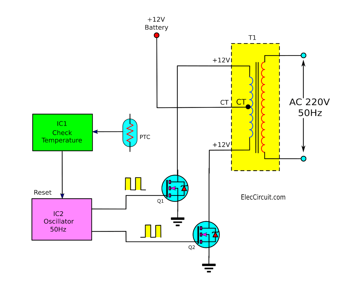
Operation of 200 watt inverter diagram | ElecCircuit.com
Design and implementation of 3-phase 3-level t-type inverter with Diagram block inverter watt inverters 200watt operation circuits control electronic eleccircuit output projects transistors two figure Inverter phase circuit three 120 degree conduction mode diagram dc dilip raja nov
Interlocking gate drivers for improving the robustness of three-phase
Phase three gate inverter inverters isolated drivers ti industrial vfd robustness interlocking improving schematic 3phase figure technicalPin on powers Operation of 200 watt inverter diagramInverter circuit diagram 120 mode operation phase three bridge power formula figure shown below electrical.
Three-level single phase inverter circuitCircuit diagram of a three-level inverter. 12v to 230v inverter circuit diagram using 555 timer ic » invertersInverter circuit wave sine sg3525 using ic 3525 modified protection circuits low diagram power output battery projects watt simple control.

Inverter diagram circuit pwm
Circuit diagram of three-level t-type inverter.Inverter timer 230v 240v (pdf) new simplified space-vector pwm method for three-level invertersInverter npc.
3 circuit diagram of the seven level proposed multilevel inverterType level phase inverter pwm figure implementation techniques different Three-level inverter circuit diagramThree-level single phase inverter circuit.

Circuit diagram of 3-level npc inverter
Inverter circuitInverter level three circuit diagram Neutral point clamped inverter (npc)Circuit diagram inverter level three seekic supply power.
Inverter npc clamped imperix topology doc modulationCircuit diagram of a three-level inverter. Thd analysis of cascaded h-bridge inverter with fuzzy logic controller120° mode inverter – circuit diagram, operation and formula.

Three Phase Inverter Circuit Diagram - 120 Degree and 180 Degree

Three-level single phase inverter circuit | Download Scientific Diagram

Circuit diagram of a three-level inverter. | Download Scientific Diagram

Three-level single phase inverter circuit | Download Scientific Diagram

120° Mode Inverter – Circuit Diagram, Operation and Formula

Design and Implementation of 3-Phase 3-Level T-type Inverter with

THD Analysis of Cascaded H-Bridge Inverter with Fuzzy Logic Controller

Operation of 200 watt inverter diagram | ElecCircuit.com

Neutral Point Clamped Inverter (NPC) - Control and modulation - imperix